
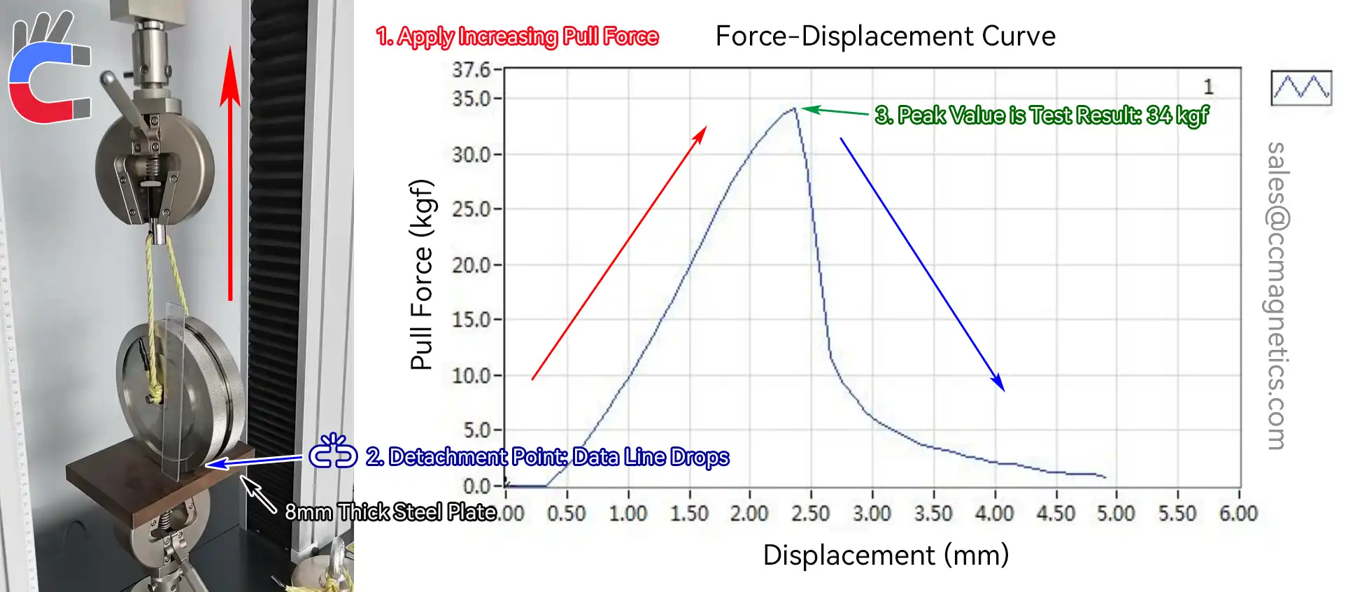
Typically, CCmagnetics provides a pull test report for each customer using our WM series of robot magnetic wheels. The test report indicates the maximum pull force. For instance, a magnetic wheel with a maximum pull force of 34 kgf, when used in a four-wheel setup with a safety factor of 4, can safely suspend 34 kg of weight. It is crucial to understand that the magnetic wheel's load capacity includes the weight of the wheel itself. Therefore, you must account for this weight when selecting wheels for your robot. Detailed formulas and calculation methods are provided later in this article.
Furthermore, the actual load capacity in real-world applications is affected by several factors. These include the slope, curvature, thickness, and material of the metal surface the robot magnetic wheel operates on, as well as the presence of any foreign objects. Whether the wheel has tires also plays a role. If you are uncertain about these factors or need help selecting the right wheel, please provide our staff with details about your robot's working environment and its total weight. Our team will be happy to assist you.
What are Robot Magnetic Wheels?
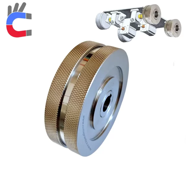
Robot Magnetic wheels are designed to adapt to various complex surface structures. Inside, they are typically made with Neodymium permanent magnets, while the exterior uses materials like stainless steel and rubber, allowing them to firmly adhere to metal surfaces.
They are essential components used in robots for specific tasks, such as:
- Ship hull cleaning robots
- Sandblasting and painting robots for shipyards
- Tank cleaning robots
- Magnetic hull crawlers
- Vessel cleaning robots
- Underwater hull cleaning robots
Their strong magnetic force allows them to stay attached for extended periods on curved surfaces of ships and the round surfaces of oil tanks. They play a vital role in maintenance work on ships, oil tanks, pipelines, and similar metal structures.

Magnetic Transmission
A key challenge when selecting magnetic wheels for wall-climbing robots is accurately calculating their vertical load capacity. However, determining the real-world load capacity of magnetic wheels isn't just based on the pull test report alone. You also need to account for the robot's specific working environment and the condition (like foreign objects and gaps) of the metal surface during the calculation.
How to Calculate Robot Magnetic Wheel Load ?
Calculating how much weight a magnetic robot wheel can hold vertically is crucial for designing safe and effective robots. Here's a breakdown:
1. Basic Definition and Formula
kgf (Kilogram-force): This unit measures force. Think of it as the force exerted by gravity on a 1-kilogram mass. In our context, 34 kgf means a single magnetic wheel can provide a maximum vertical holding force equivalent to the weight of about 34 kg (which is roughly 333.2 Newtons or N).
Suspension Capacity Calculation:
The maximum weight you can safely suspend using a magnetic wheel is calculated using its pull force and a Safety Factor (SF).

2. Choosing the Safety Factor (SF)
The Safety Factor is a multiplier used to build in a margin of safety, accounting for variations and unexpected forces. A higher SF means a greater safety margin. Here are some recommendations:
| Scenario | Recommended Safety Factor (SF) | Explanation |
|---|---|---|
| Static Load | 2 - 3 | For stationary use. Accounts for material fatigue. |
| Dynamic Load | 4 - 5 | For moving robots. Considers inertia, vibration, etc. |
| High-Risk Areas | ≥6 | Ensures safety even in extreme conditions (e.g., high altitude work). |
3. Single Wheel Suspension Capacity
Let's calculate the safe capacity for a single wheel:
Example: A 34 kgf magnetic wheel used in a dynamic operation (using SF=4).
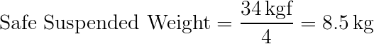
Note: This 8.5 kg is the safe weight portion of the robot that one wheel can support.
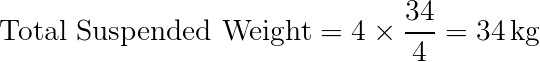
4. Total Vehicle Suspension Capacity
If your robot uses multiple wheels (like a four-wheel design), the total suspension capacity is the sum of the safe capacity of each wheel.

Where n is the number of wheels.
Example: A four-wheel robot using four 34 kgf wheels for dynamic tasks (SF=4).
5. Real-World Adjustments
The calculations above provide a baseline. In practice, you need to adjust based on the actual working environment:
(1) Operating on Sloped Surfaces
When climbing slopes (like on a ship hull), gravity pulls the robot downwards, reducing the effective magnetic force available for vertical support.
On a slope with angle θ, the effective holding force is reduced by the cosine of the angle.

Example: On a 30° slope, with a total magnetic force of 136 kgf (from 4 wheels) and SF=4.

(2) Impact Loads (Sudden Stops/Starts)
If your robot needs to stop or accelerate quickly, the inertia creates additional forces (impact loads) that the magnetic grip must withstand. This effectively increases the load.
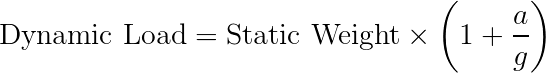
Where:
- a is the acceleration/deceleration.
- g is the acceleration due to gravity (approx. 9.8 m/s²).
Example: A 34 kg robot static weight experiencing an acceleration of a=3m/s².

6. Engineering Recommendations
-
Load Matching:
To safely suspend a robot weighing 34 kg:
- For dynamic scenarios: You'd need at least a total capacity matching the
Total Suspended Weightcalculation (e.g., 4 wheels @ 34 kgf with SF=4). - For static scenarios: You might need less (e.g., 2 wheels @ 34 kgf with SF=2), but consider safety.
- For dynamic scenarios: You'd need at least a total capacity matching the
-
Redundancy: It's often recommended that the total available magnetic force is at least 5 times the target weight. This provides significant buffer for unexpected forces or surface issues.
-
Field Testing: Always verify the actual holding force using a pull force gauge on the target surface. Laboratory data can sometimes overestimate performance in real-world conditions.
7. Quick Reference Table
Here's a simple table based on a 34 kgf wheel for quick estimates:
| Single Wheel Magnetic Force (kgf) | Safety Factor (SF) | Single Wheel Safe Capacity (kg) | Four-Wheel System Total Capacity (kg) |
|---|---|---|---|
| 34 | 2 | 17 | 68 |
| 34 | 4 | 8.5 | 34 |
| 34 | 6 | ≈5.7 | ≈22.8 |
Factors Affecting Robot Magnetic Wheel Performance and Your Safety Factor
While the pull test provides a baseline, several real-world factors influence the actual magnetic force and the Safety Factor you should use:
-
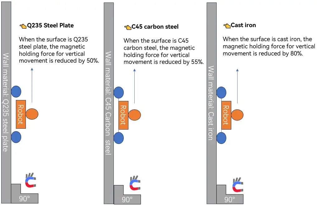
Metal Surface Properties:
- Thickness and Grade: Generally, the metal surface should be thicker than 5mm for the magnetic wheel to achieve its full potential pull force. However, the specific type or 'grade' of metal also matters significantly. Different metal alloys, like various steel grades (e.g., Q235 steel vs. others), will result in different adhesion forces.
-
Gap Between Wheel and Surface:
- Any gap between the magnetic wheel and the metal surface, often caused by the wheel's tire, rust, paint, or debris, will reduce the magnetic pull.
- The larger the gap, the weaker the suction.
- At CCmagnetics, we have extensive experience and data on how gaps affect magnetic wheel suction, backed by data from numerous customer projects. We openly share this knowledge to help our clients.
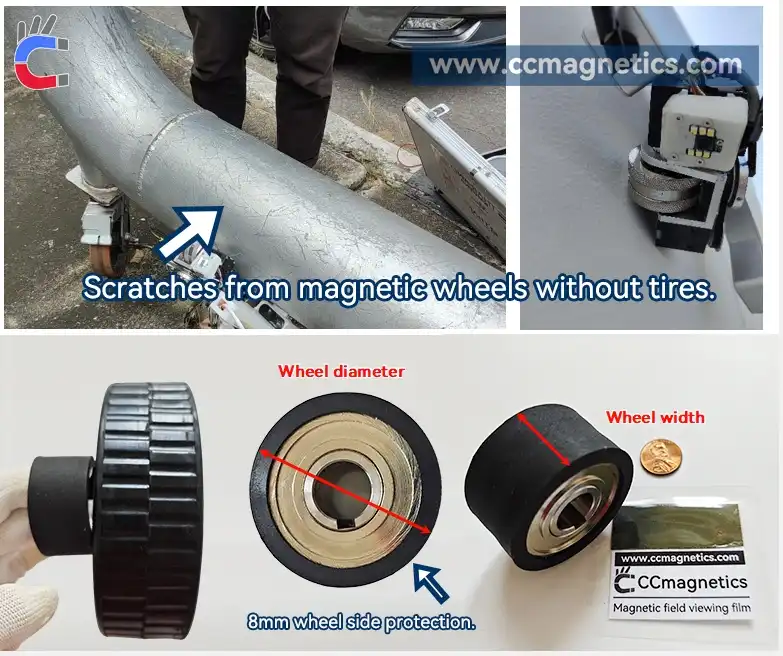
Robot Magnetic Wheel Tire
Other Magnetic Wheel Selection Tips
- Width Matters More Than Diameter: A common misunderstanding is that a larger outer diameter of the robot magnetic wheel means stronger pull. This isn't the primary factor. The actual pull force is mainly determined by the width of the wheel and the grade of the magnets used inside. A wider wheel means a larger magnetic contact area with the metal surface, which significantly increases the load capacity.
If you are designing a robot vehicle and are unsure about calculating the required load capacity for your magnetic wheels, please feel free to contact our sales team. We are here to help you determine the best solution for your application.